Fatigue testing of reinforced-concrete steel bars
1. Introduction
The fatigue strength of reinforced concrete bars has been the subject of research for many years. Usually the fatigue characteristics of reinforced-concrete steel bars are studied with axial fatigue tests using conventional testing machines and specimens in the as-delivered state, usually ribbed rods. The advantages of axial tests include low costs at a relatively high testing frequency (up to 200 Hz) and the possibility of defining test conditions precisely. A very significant disadvantage is related to problems connected with clamping bars in testing machines, where local stresses in bar clamping areas are responsible for the premature failure of the bars. It is also difficult to avoid the effect of secondary stresses caused by the non-recti linearity of specimens or their misalignment in testing machine jaws [1]. A number of studies [2-4] contain information about various methods to prepare the grip parts of specimens usually connected with using an added layer between a specimen and a testing machine jaw and /or slight machining of specimen ends. Some of these include the use of leather belts wrapped around the specimen grip part, low melting point metallic fillings, resins and aluminum pads. However, little information is available concerning the effectiveness of the measures mentioned. Bars and ribbed rods made of B500SP steel are used for reinforcing concrete elements and structures designed in accordance with the specifications in EN 10080 [5] for C class steels of a yield point of 500 MPa. The requirements for fatigue strength tests are described in EN 10080 and EN 1421- 3 [6] and are summarized below:
· Maximum stress, σmax=300 MPa,
· Stress amplitude, σa=150 MPa,
· Load cycle frequency, 1-200 Hz,
· Acceptance criterion, failure-free after 2∙106 load change cycles
2. Experimental
High cycle fatigue tests were conducted on reinforced-concrete steel 8, 12 and 20 mm diameter bars (Figure 1) to study their behaviour under axial tension loading according to EN 10080 and EN 1421-3 using a 100kN capacity Instron machine (Figure 2) until cracking or reaching the boundary number of cycles of 2∙106

Reinforced-concrete steel 8, 12 and 20 mm diameter bars.
1 Figure
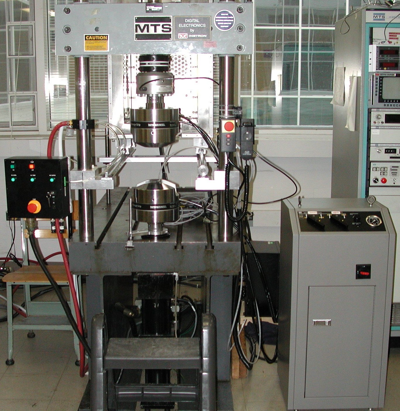
100kN capacity Instron fatigue testing machine
Figure 2
The maximum and minimum loads were calculated so as to agree with the EN specifications of maximum stresses of σmax=300 MPa and minimum stresses of σmin=150 MPa. The load cycle frequency was set at 25 Hz. Hardness and tensile tests were also carried out so as to determine whether the material was in agreement with the EN standards concerning concrete steel bars. The chemical composition of the material was determined using optical emission spectroscopy and the steel microstructures were studied using optical and scanning electron microscopy (SEM) to investigate the presence of inclusions that could lead to premature failure during testing. The fracture surfaces of the mechanical tests were further studied using scanning electron microscopy to obtain a better picture of the failure process. 3. Results and Discussion The chemical composition of the steel bars tested is presented in Table 1 and the mechanical test results are given in Table 2. Both are in agreement with the EN specifications so any failure during testing could not be attributed to poor quality of thematerial.
Table 1.Chemical composition of steel bars
|
Bar diameter (mm) |
%C |
%Mn |
%Si |
%S |
%P |
|
8 |
0.22 |
0.57 |
0.16 |
0.045 |
0.024 |
|
12 |
0.21 |
0.56 |
0.15 |
0.043 |
0.023 |
|
20 |
0.21 |
0.57 |
0.15 |
0.043 |
0.022 |
Table 2. Mechanical tests results
|
Bar diameter (mm) |
Yield Strength (Mpa) |
Tensile Strength(Mpa) |
% Elongation |
VPN |
|
8 |
531 |
641 |
29 |
213 |
|
12 |
534 |
634 |
30 |
211 |
|
20 |
497 |
625 |
28 |
208 |
The fatigue tests of bars in the as-delivered state, that is without any preparation of the specimen grip parts, varied depending on the bar diameter Tables 3-5. The testing parameters were calculated according to EN 1421-3 and the tests were carried out at a load cycle frequency of 25 Hz for a maximum of 2*106 cycles.
Table 3. Fatigue Test of 8mm bars
(Fmax =15.072 N, Fmin=7.536 N, Fmean=11.304 N, Famplitude=3.768 N)
|
Specimen |
Nominal diameter (mm) |
Length (mm) 140,14d |
Failure (yes/no) |
|
Φ 8-1 |
8 |
140 |
no |
|
Φ 8-2 |
8 |
140 |
no |
|
Φ 8-3 |
8 |
140 |
no |
|
Φ 8-4 |
8 |
140 |
no |
|
Φ 8-5 |
8 |
140 |
no |
Table 4. Fatigue Test of 12mm bars
(Fmax =33.912N, Fmin=16.956N, Fmean=25.434N, Famplitude=8.478N)
|
Specimen |
Nominal diameter (mm) |
Length (mm) 140,14d |
Failure (yes/no) |
|
Φ 12-1 |
12 |
168 |
yes 934331 cycles |
|
Φ 12-2 |
12 |
168 |
no |
|
Φ 12-3 |
12 |
168 |
no |
|
Φ 12-4 |
12 |
168 |
no |
|
Φ 12-5 |
12 |
168 |
no |
|
Φ 12-6 |
12 |
168 |
yes 934331 cycles |
|
Φ 12-7 |
12 |
168 |
yes 964063 cycles |
|
Φ 12-8 |
12 |
168 |
no |
Table 5. Fatigue Test of 20mm bars
(Fmax =94.200, Fmin=47.100N, Fmean=70.650, Famplitude=23.550N)
|
Specimen |
Nominal diameter (mm) |
Length (mm) 140,14d |
Failure (yes/no) |
|
Φ 20-1 |
20 |
280 |
yes 1088570 cycles |
|
Φ 20-2 |
20 |
280 |
yes 1854310 cycles |
|
Φ 20-3 |
20 |
280 |
yes 1115141 cycles |
|
Φ 20-4 |
20 |
280 |
yes 675589 cycles |
|
Φ 20-5 |
20 |
280 |
yes759420 cycles |
As can be seen all five bars of eight millimetre diameter withstood the required number of 2∙106 cycles when tested at a frequency of 25Hz. However, when the 12 mm bars were tested a number of specimens failed usually within or very near the grip jaws (Figure 3). Moreover, all (10/10) specimens of 20 mm diameter failed and this caused suspicion about the quality of the bar material.
Figure 3. Premature failure within or near grip jaws

To exclude any such possibility the steel microstructures were studied using optical microscopy (Figure 4). As can be seen all diameter bars exhibited a ferrite - pearlite microstructure and no martensite or other phases were present that could account for the premature failure observed.

Figure 4. Steel microstructure, top x400, bottom x1000
As expected, the fracture surface observed using scanning microscopy revealed the presence of manganese sulphide inclusions (Figure 5) but this cannot by itself explain why premature fracture occurred only in the 12 and 20 mm bars. Studying the literature showed that fatigue strength of concrete steel is diameter dependent [1, 7-9]. Steel bars of smaller diameter exhibit higher fatigue strength than steel bars of the same quality but bigger diameter. In German standards for concrete steel a gradual reduction in the requirements for fatigue strength is reported and in BS 4449 [9] the specifications differ depending on group diameter as shown in Table 6
Figure 5. Fracture surfaces observed using SEM showing manganese sulphide inclusions
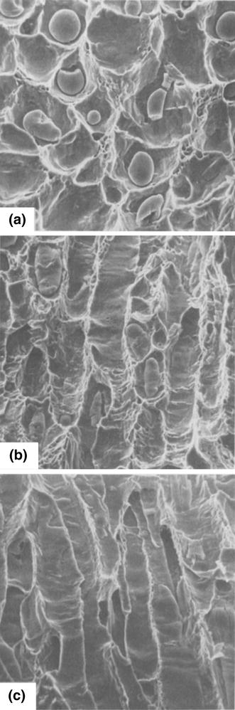
Table 6. Fatigue test specifications according to BS 4449:2005
|
Bar diameter (mm) |
2σΑ (MPa) |
σmax (MPa) |
2σm (MPa) |
|
≤16 |
200 |
250 |
150 |
|
>16, ≤20 |
185 |
230 |
137,5 |
|
>20, ≤25 |
170 |
215,5 |
127,5 |
|
>25, ≤32 |
160 |
200 |
120 |
|
32 |
150 |
187,5 |
112,5 |
In the present study the results appear to agree with the above and originally the differences in fatigue strength of the 12 and 20 mm bars in relation to that of the 8 mm ones was attributed to their larger diameters. However, a closer look at the bibliography [2-4, 10-12] reveals that premature failure inside or close to the fatigue machine grips is a common problem with fatigue testing of reinforcing bars. This is due to the difficulties related to the fact that fatigue cracks are usually generated in the area where test specimens are fixed in the jaws of a testing machine, i.e. where significant notches are present. Thus, the results of such tests cannot be regarded as reliable and should or may be rejected according to the EN 1421-3. Tilly [2] reports information about numerous attempts to properly prepare the grip parts of specimens so as to eliminate the problem of crack initiation in the grip part of the specimens; such attempts were always connected with using an additional layer between a specimen and a testing machine jaw. He [2] mentions the use of leather belts wrapped around the specimen grip part, low melting point metallic fillings, resins and aluminium pads. However, Tilly [2] does not provide any information concerning the effectiveness of the measures mentioned. Krzysztof Krasnowski [3] mention a successful method that was used to eliminate the problem but do not give any information of the steps taken. In addition, in the NordTest method for fatigue testing of concrete reinforcement steel bars [4] four different methods for preparing the grip parts of specimens are described in detail. However, they all seem rather complicated and/or timeconsuming. In order to locally change stresses in the specimen grip area and to make the notches caused by the jaws too small to lead to the premature failure the following technique was used with surprising success in the present study. For the 20 mm bars, firstly, a 50 mm length of the specimen ends was turned to 19.5 mm diameter, until the relief on the surface was almost completely removed. There was also a 4 mm long curved part machined past the grip part (Figure 6).

Figure 6. Machined specimen ends.
This resulted in a larger surface area being gripped by the machine jaws and eliminated the applied stress concentrating on only four or five points that may cause failure. Then, approximately 0.5 mm of aluminium, 5 cm wide, tape was wrapped around the specimen ends to reduce the depth of the notches caused on the specimen surface by the machine jaws part (Figure 7).

Figure 7. Specimen ends wrapped with aluminium tape.
The fatigue test results of such specimens showed that none of the required five, as per EN 1421-3, failed. Therefore, the problem with specimen failure was not due to material quality but specimen surface morphology that results in stress concentration and notch creation caused by the machine jaws.
The etiology of the bars’ premature failure can be investigated through Finite Element Modelling techniques which is a widely accepted approach for engineering components and materials [13] if the model is properly verified/validated [14]. The use of non-linear properties [15] allows in this case not only the determination of critical stress concentrations but also the propagation of the initiated failure. 4. Conclusions High cycle fatigue tests conducted on reinforced-concrete steel ribbed rods in accordance with the specifications in EN 10080 are difficult to perform due to premature failure appearing within or near grip jaws. Specimen pretreatment [16] has been effective in prolonging the life cycle of several engineering components. In the same way, the presented preparation method described above will aid researchers on fatigue testing to obtain accurate test results and save on material and time.
References
[1] Sismanis P. and Mastorakis A., 5-7 Nov 2008, Fatigue strength of concrete-reinforcing steel bars, Panhellenic Conference of Anti-Sesmic Mechanics, article1785
[2] Tilly G. P., 1979, Fatigue on steel reinforcement bars in concrete: a review. Fatigue of Engineering Materials and Structures, no. 2, pp. 251-68
[3] Krasnowski K., 2015, Concrete-reinforcing Steel Bars – Applications and Fatigue Tests, BIULETYN INSTYTUTU SPAWALNICTWA, No. 1, pp.13-20
[4] NordTest method, 1989, STEELS FOR CONCRETE REINFORCEMENT:AXIAL LOAD FATIGUE TESTING OF BARS, ΝΤ mech 014
[5] ΕΝ 10080, 2005, Steel for the reinforcement of concrete - Weldable reinforcingsteel
[6] EN 1421-3, 2007, Steel for the reinforcement of concrete – Weldable reinforcing steel – Part 3: Technical class B500C
[7] DIN 1045-1:2001-07, Concrete, reinforced and pre-stressed concrete structures - Part 1: Design and construction
[8] DIN 488-1: 2009-08 Betonstahl - Teil 1: Stahlsorten, Eigenschaften,Kennzeichnung
[9] BS 4449:2005+A2:2009, Steel for the reinforcement of concrete. Weldable reinforcing steel. Bar, coil and de-coiled product
[10] Bannister J. L. 1975, Fatigue resistance of reinforcement for concrete. Proc. Conf. Underwater Construction Technology, Department of Civil and Structural Engineering Report, University College, Cardiff
[11] Burton K. T. and Hognestad E., 1967, Fatigue tests on reinforcing bars - tack welding of stirrups. ACIJ. 64, pp. 244-52
[12] Walker E. F., Austen I. M., Harrison T. C. and Morley J., 1975, Fatigue and corrosion fatigue of reinforcement bars, Proc. Conf. Underwater Construction Technology, Department of Civil and Structural Engineering Report, University College, Cardiff
[13] Bouzakis K. D., Efstathiou K., Paradisiadis G., Tsouknidas, A: Experimental and FEM-supported investigation of wet ceramic clay extrusion for the determination of stress distributions on the applied tools' surfaces. Journal of the European Ceramic Society, 2008, vol. 28, issue 11, pp. 2117-2127.
[14] Tsouknidas A., Savvakis S., Asaniotis Y., Anagnostidis K., Lontos A., Michailidis N.: The effect of kyphoplasty parameters on the dynamic load transfer within the lumbar spine considering the response of a bio-realistic spine segment. Clinical Biomechanics, 2013, vol. 28, issue 9- 10, pp. 949-55.
[15] Bouzakis K.D., Maliaris G., Tsouknidas A.: A FEM supported semi-solid high pressure die casting process optimization based on rheological properties by isothermal compression tests at thixo temperatures extracted. Computational Materials Science, 2012, vol. 59, pp. 133- 139.
[16] Bouzakis K. D., Bouzakis E., Skordaris G., Makrimallakis S., Tsouknidas A., Katirtzoglou G., Gerardis S.: Effect of PVD films wet micro-blasting by various Al2O3 grain sizes on the wear behaviour of coated tools. Surface and Coatings Technology, 2011, vol. 205, issue suppl. 2, pp. S128-S132
[17].International Engineering Research and Innovation Symposium (IRIS)
Posted on 2021/02/04 07:05 PM